Sleeving - yet another attempt!
My 4-pin auxiliary power cable was an improvement, but it still had issues- I made just a bit too short, and the small sleeve was coming out of the connector in one place. I found and joined overclock.net, which has lots of good forums, guides and how-tos.
As before, I used a set of wires with connectors salvaged off an old power supply. |
|
It was tight fitting the sleeve and heat shrink. In fact, I did not have to heat the heatshrink- I just lined it up with the end of the outer sleeve.
The outer ends of the cable were much easier to sleeve. |
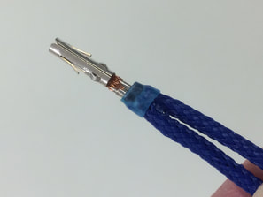
One guide taught me about melting the sleeve at the end and pressing it onto the crimp. This was helpful for these two wire connections on the molex plug. Finished it off with a small amount of heat shrink.
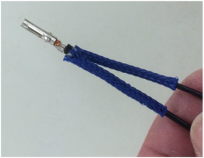
1/8 inch sleeve was used on the individual wires. I sized and cut 3/8" sleeve for the bundle. I carefully worked heatshrink and sleeve over the loose pins and wire. I left the sleeve loose until after finishing the other connector.
|
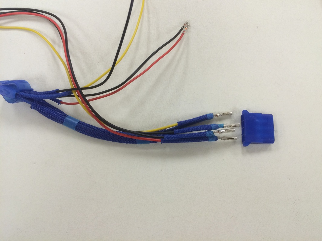
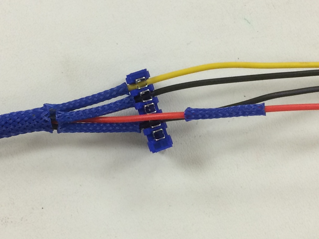
The old power supply cables are color coded: Yellow-12V, Red-5V, Black-ground. Missing is Orange-3.1V
|

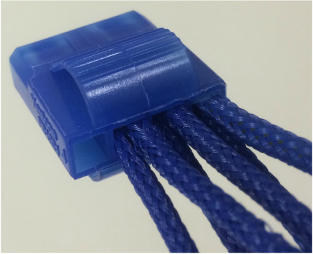
My SATA connectors are crimp-less, so nothing for the sleeve to adhere to. Another tip from OCN- super glue with a brush on applicator! Brush a small amount on the wire, and stick the sleeve in place. The brush is easier to use for this instead of the conventional nozzle, and I found a bottle at the local big-box hardware store for a good price.
|
|
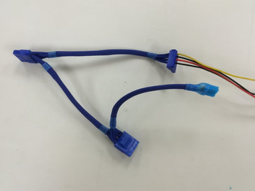
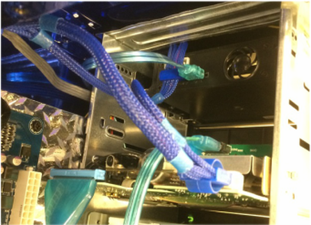
The left connector plugs into the power supply. Have to use a conventional molex connector here instead of the larger EZ-grip connector that I prefer. The EZ-grip at the bottom plugs into my floppy, and the cable terminates with a berg connector to my optical drive. Another OCN tip, use heat shrink over the end of the small berg connector to hide the wires! Works for fan connectors and motherboard headers too!
The upper cable then goes to my SATA bay in the top of my case, and the unsleeved wires continue up and around behind the drive bays to power my LED lights. Wiring for the lights is hiding behind the motherboard tray. So here's a comparison of the old cable with the new. |
You might notice 4 wires and not 5 going to/from the SATA connector. My old power supply does not have 3.1V for SATA Power, I don't need it currently.
|
Old power supply cable to floppy and optical drive
|
New cable to floppy, optical; SATA then up and around to the back
|
And, since I mentioned the wiring under the motherboard tray, here's a comparison of my old and new versions.
|
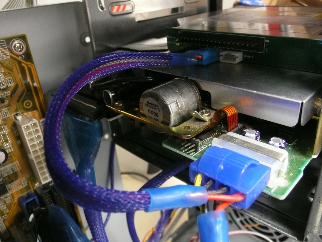
I have two switches (top) to control my CCFL UV lamps (12v) and my illuminated case feet (5v). Power comes from the power supply on the right. All this gets crammed under the motherboard to hide things. (This could potentially be a problem.)
I was never satisfied with this configuration below. The motherboard pressed against the molex connector 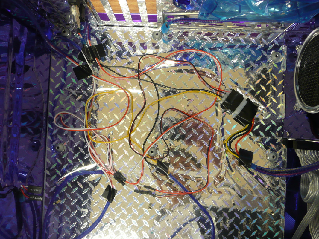
Old version
|
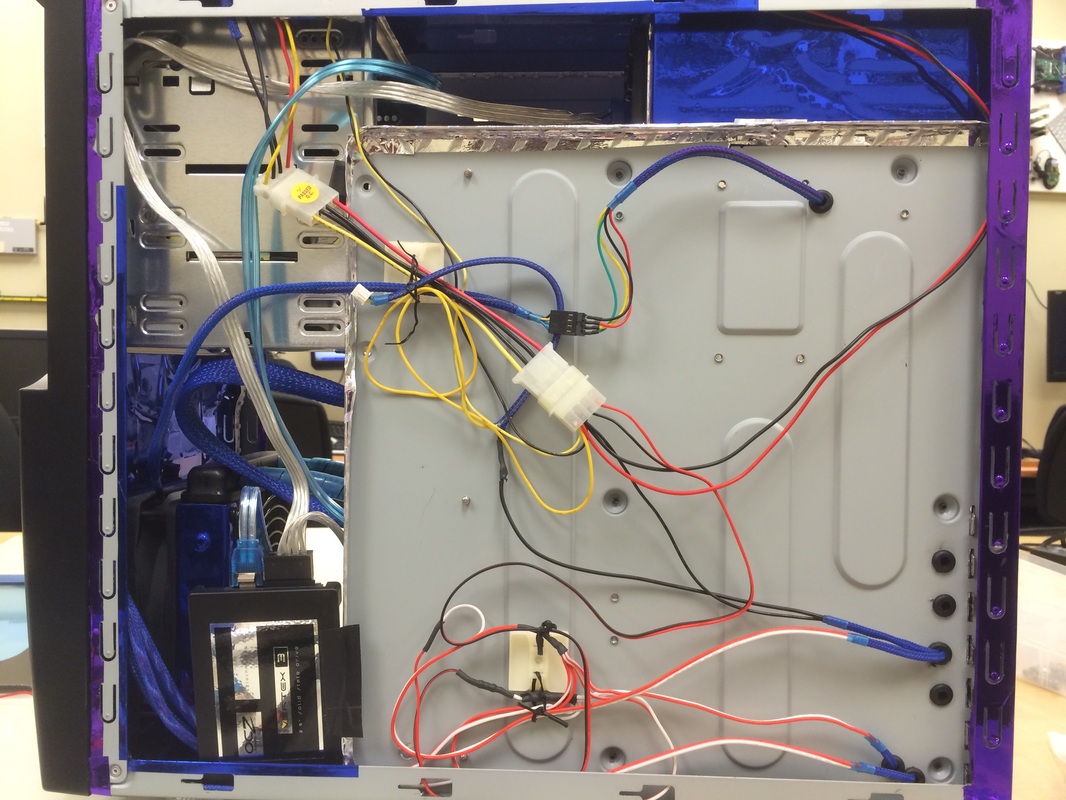
New version
To move the wires underneath the tray, I had to drill a few holes and insert some rubber grommets to protect the wires from being cut on the sharp metal. (This was done with the motherboard removed.) I drilled some extras for flexibility and future use. The back case feet LED wires come through the bottom hole. There's a lot more room for the wiring now. Power comes in on the upper left behind the drive bays (which is where the CCFL inverter used to be hidden.
|
It still looks a bit messy right now, but once I'm finished with my lighting, I'll redo the wiring and clean it up.
|
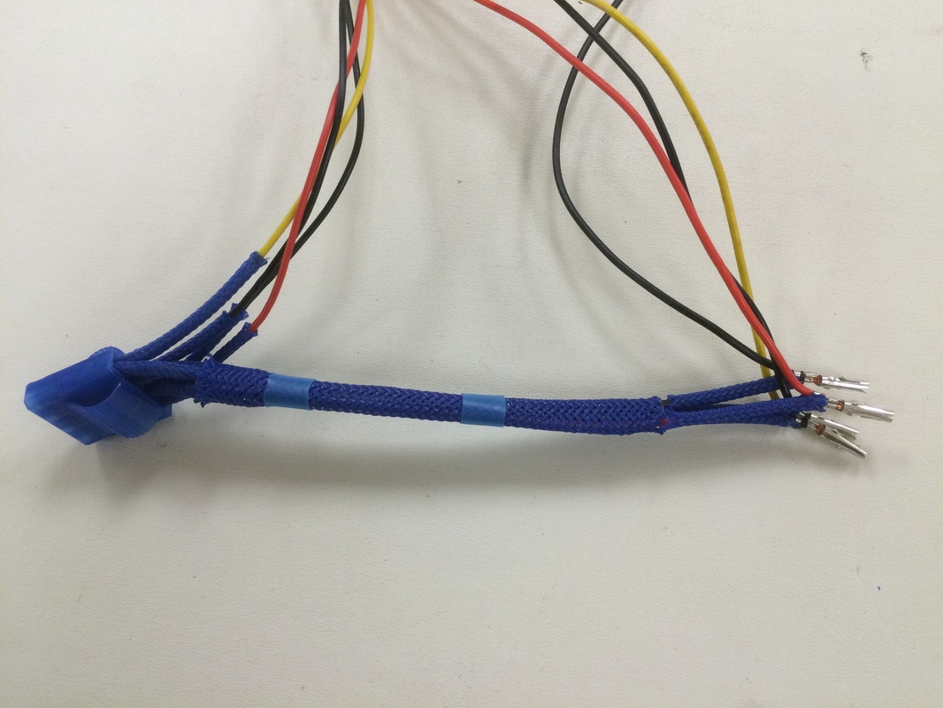
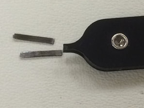
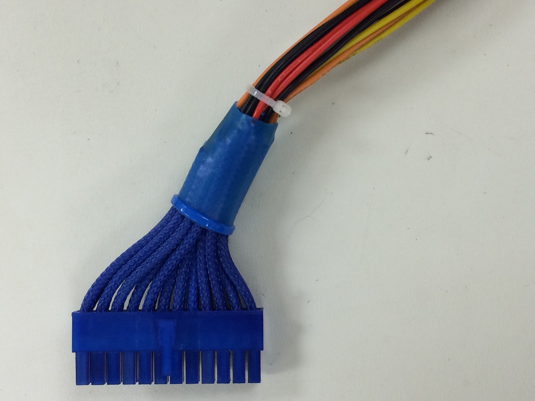
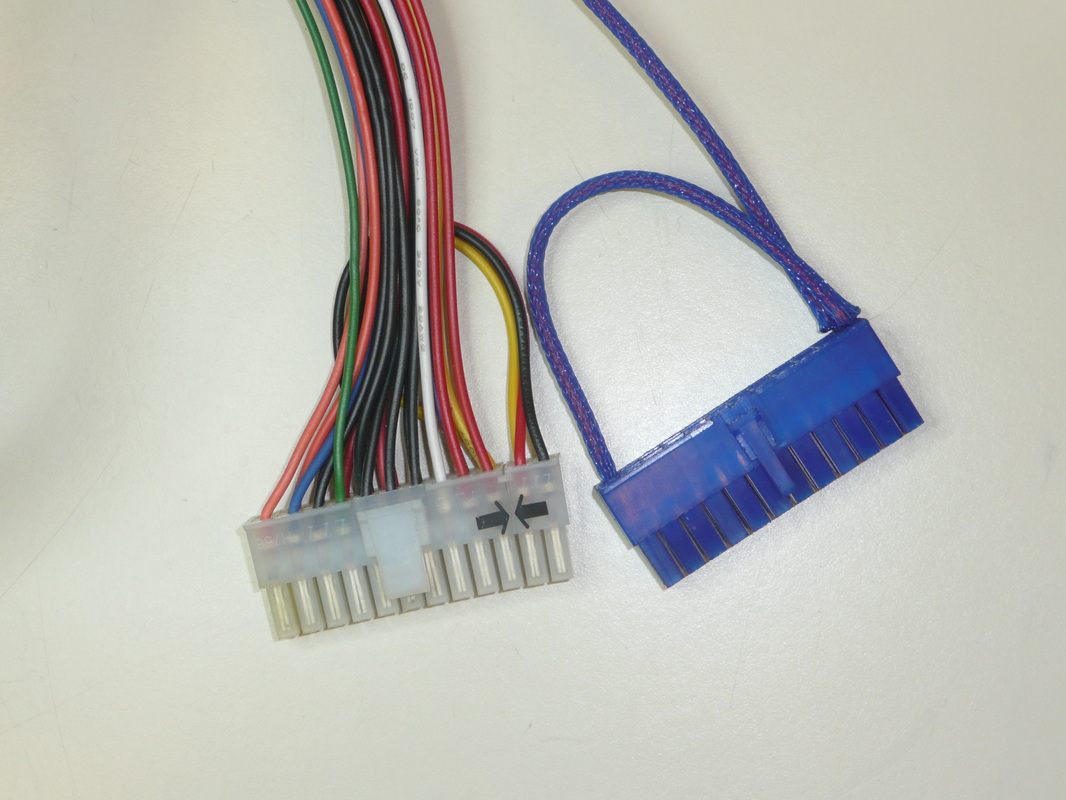
One end of my power cable is now completed. My earlier attempt was frustrated when I had problems removing the pins from my donor cable. When my de-pin tool broke, it was actually easier to depin! My old power supply was 20 pin, and the extra wire loops were for the 4-pin extension. My new power supply is 24 pin, so the cable is now one-to-one.
So my plan is to measure and cut each individual wire to length. Wires to the top of the connector will be shorter than wires going to the bottom. Then I will put on the sleeving, crimp the connectors and finish it off. |
|
Halfway done with second version
|
1st attempt didn't get too far!
|
